How to Prepare Power Electronics for GATE ESE PSU’s
INTRODUCTION (Power Electronics for GATE)
Hello everyone. Welcome to Neospark. Today we will be discussing how to prepare Power Electronics for GATE Electrical Engineering as well as Power Electronics and Drives for ESE Electrical Engineering. At the onset, you should know that Power Electronics is a massive area in terms of content and research prospects, and out of this a very small fraction is needed for GATE and ESE. An aspirant should not waste time on unnecessary things while studying this subject. If you gain interest in this subject while studying it, remember that there are other subjects as well in the syllabi that are equally important, and available time is limited.
Power Electronics is a core subject for Electrical Engineering and having a good knowledge of this subject would prove beneficial for higher studies. Most people preparing for GATE EE find this difficult as conceptual clarity is highly important here. However, content-wise for GATE, the syllabus for Power Electronics is comparatively lesser than the other core subjects – Electrical Machines and Power Systems and so it takes less time to cover compared to those.
There have been a few changes in the syllabus for Power Electronics for GATE 2021 compared to 2016 which have been highlighted in the respective modules for each topic. First, we will talk about the prerequisites for studying this subject which are:
- Network Theory – This is absolutely necessary and without a very strong grip on Networks, don’t start power electronics. The significant topics needed are the basics of inductors and capacitors (highly important) and their properties, AC circuit analysis, 3-phase systems including waveforms and phasor relations (highly important), and transient analysis (highly important). You can avail of only the AC Circuit Course on the Neospark Platform. Click here
- Signals and Systems – Knowledge of the Fourier Series in full detail and basic signals including calculation of average and RMS values is needed.
- Analog Electronics – DC analysis of diode circuits is essential. Also for the inverter part, working of op-amp as a comparator is needed for the PWM part.
- Electrical Machines – Not a necessity from a GATE point of view. Complete knowledge of all motors – DC, induction, and synchronous is essential for the portion of the drive which is a part of the ESE syllabus. Also note that recently in GATE, questions are being asked that require knowledge of multiple subjects, and a good possibility of questions combining concepts of Power Electronics with Electrical Machines is there. So it is better to complete Machines before PE although it’s not a prerequisite for GATE.
- Control Systems – For the topic state space analysis of DC-DC converters only for an advanced student. Someone struggling with Power Electronics can skip this.
Next, for self-study students, the various references to be followed are:
- Power Electronics by M.H. Rashid
- Power Electronics by M.D. Singh and K.B. Khanchandani
- Power Electronics by P.S. Bimbhra – Please note that this book has many errors but has a large variety of good numericals both solved and unsolved. Also, some particular topics that can’t be found in other books can be found here.
- Power Electronics by Ned Mohan – This book is usually very difficult to follow by an average student or a beginner. But some topics can be found here only and should be referred for them only.
- Power Electronics by Daniel W. Hart – Only for topics not found or given well in other books
- Fundamentals of Electric Drives by G.K. Dubey – Only for ESE
Note: The above books are needed if you are studying power electronics by self-study. If you are Studying from Neospark Subjectwise Course of Power Electronics then Sohail Sir covered all the necessary concepts. Click here for details

(Power Electronics for GATE)
Normally, it should take 1 month to cover this subject for GATE and 2 months for GATE + ESE. We break down each module of PE one by one.
PE DEVICES(Power Electronics for GATE)
For this portion, you can refer to either books 1 and 2 and for some portions no 4.
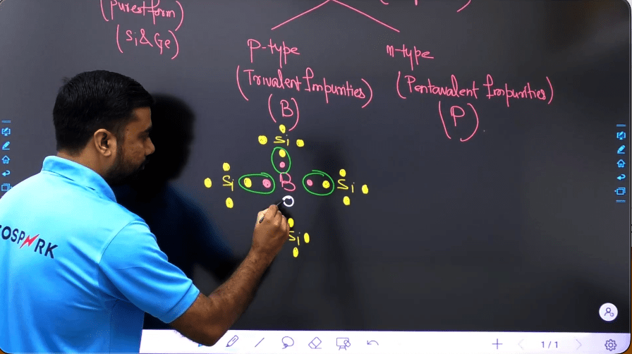
First, you need to study what are ideal and practical switches and the differences between them. Then we learn to classify switches from different viewpoints and their regions of operation. Then we cover each power electronic device as a switch starting with the Power Diode. As per the new syllabus for GATE, only static V-I characteristics and different firing and gating circuits are needed for GATE. However for ESE, for power diodes, the various types and their switching characteristics are to be studied.
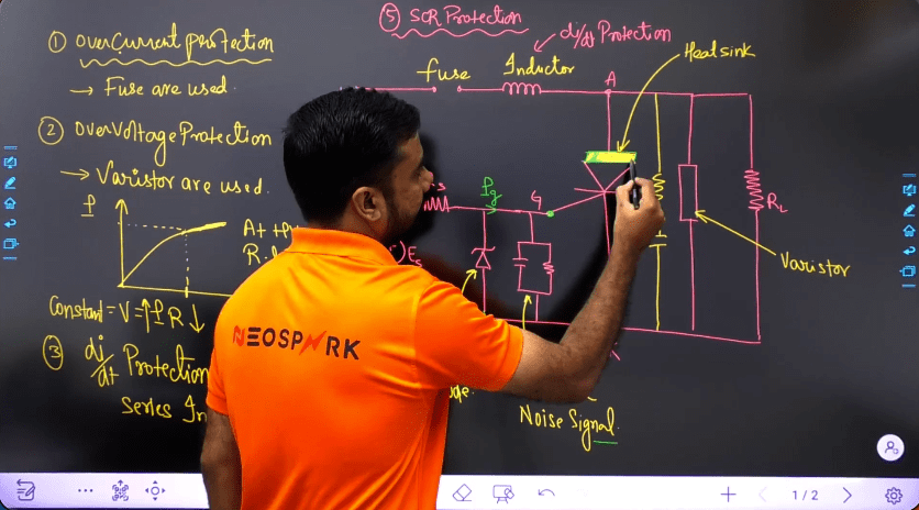
Next comes the most important device which is SCR. For GATE, only V-I characteristics, triggering methods, ratings, protection, firing circuits including pulse transformer, gate drive circuits, and series and parallel operation this much are needed. For ESE, switching characteristics and device details need to be covered too.
The other 2 devices in the GATE syllabus are Power MOSFET and IGBT. For these, only modeling, properties, V-I static characteristics, and firing circuits are needed. The book by Rashid can be followed for this. For ESE, switching and device details are there. Also, other devices need to be covered in the same way for ESE namely Power BJT, GTO, Triac, etc.
The last part of this module deals with some preliminaries like average and RMS values and Fourier analysis of standard waveforms that we encounter in Power Electronics.
Explore Neospark Power Electronics for GATE Course
(Power Electronics for GATE)
AC-DC CONVERTERS (Power Electronics for GATE)
This is the largest part of the GATE PE syllabus. However, it is also the easiest. The most challenging part is simplifying the huge no of formulae that are involved in this part. However, dealing with formulae has been a piece of cake in the Power Electronics 3.0 Course by Sohail Sir. Also, it is essential to master how to draw various waveforms to answer tricky and conceptual questions correctly. First, we study classify rectifiers on the basis of configuration and number of pulses.
Also, we study the classification of loads as voltage stiff and current stiff and how power consumed is calculated for each load. We study each separately for both uncontrolled and controlled cases. The various configurations to be studied for both uncontrolled and controlled are:
- 1 phase half wave rectifier for the following loads – R, L, C, RL, RE, RLE, and LC(only uncontrolled is enough for LC). Also the use of a free-wheeling diode in this regard and how continuous conduction mode (CCM) can be achieved through it. You can refer to references 1 and 2 for this. The Diode LC circuit is highly important as it will have multiple uses while studying commutation circuits.
- 1 phase full wave rectifier for the following loads – R, RL, RE, and RLE. Both the bridge rectifier and center-tapped transformer rectifier are to be covered. When load inductance is present, the conditions for CCM and discontinuous conduction mode (DCM) are to be studied as well. The most important part is the controlled rectifier with continuous ripple-free load current (pure DC) and should time fall short during preparation, only this case would be the most important.
- 1 phase semi-converter – study the 3 configurations which are symmetrical, asymmetrical, and full wave rectifier with a freewheeling diode for CCM case with ripple-free load current. Note the similarities and differences between them. A brief study if time permits can be done on the DCM case too.
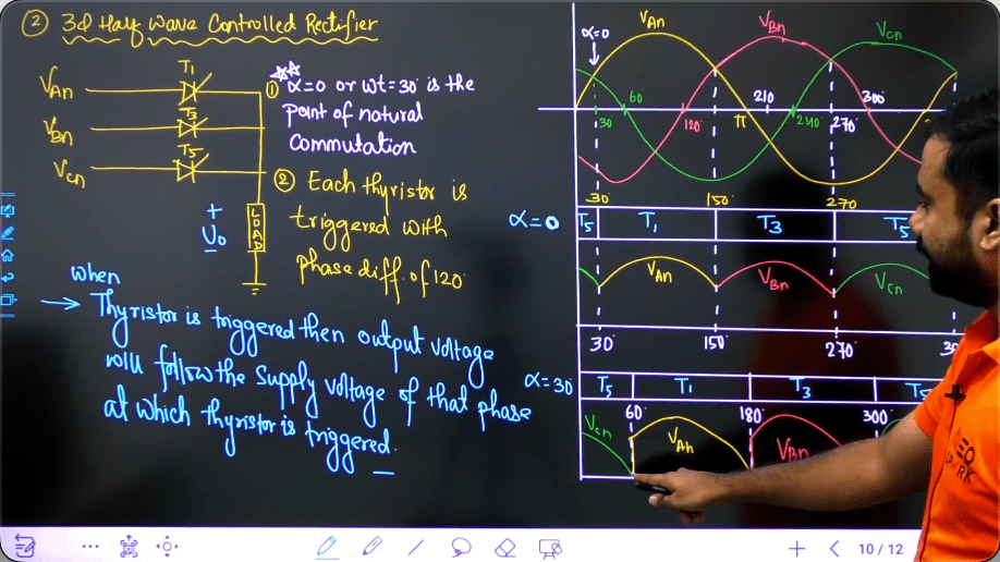
- 3 phase half wave rectifier / 3 phase full wave rectifier / 3 phase semi converter – For all the 3 cases of 3 phase rectifier, you need to focus on the CCM case with ripple-free load current. The case with free-wheeling diode is to be studied as well. If time permits study the case of pure R load and focus on the ranges of firing angles where it is under CCM and DCM respectively. Sometimes RE load can be asked too. It’s not possible to remember the results of so many cases so it is essential you know how to draw the waveforms to deal with miscellaneous cases.
For each of the configurations studied above the following things must be known and calculated :
- Fourier analysis of input current of full wave converter and semi-converter for both 1 and 3 phases only for the case of CCM with ripple-free load current. Harmonic analysis must be done and computation of distortion factor g, total harmonic distortion or THD, fundamental displacement factor, input power factor, and crest factor must be known.
- For each case wherever applicable, calculations must be known for average and RMS values of output voltages and currents, output power, rectification efficiency, transformers utilization factor (TUF), form factor (FF), voltage and current ripple factors, extinction angle, conduction angle/time of each device, peak inverse voltage (PIV) and other ratings of each switch, circuit turn-off time, minimum and maximum possible firing angles and fundamental reactive power input to the rectifier (only for full converter and semi-converter for both 1 and 3 phases).
- An advanced student can also cover the concepts of the waving effect and commutation requirements in these rectifiers but if time is short, it is advisable to skip it. Also for ESE, you can cover the use of various 3-phase transformer connections at the input of these rectifiers and also the general case of n-pulse rectifiers.

(Power Electronics for GATE)
Then we study the effect of source resistances and inductances on the operation of these rectifiers. Here the discussion is to be limited to CCM only. The concepts of overlap angle, change in output voltage, fundamental displacement factor, and voltage regulation due to source inductance are to be covered.
It is very difficult to memorize the formulae for RMS output voltages for all the cases and it’s not needed too for most cases. Remember the case for a one-phase full wave rectifier for RMS output voltage as it is the only case for RMS output voltage asked in previous years’ questions till now.
We sum up this module by saying that focus on how to draw waveforms the most as if you can do that, you can solve 100% questions correctly from here.
DC-DC CONVERTER (Power Electronics for GATE)
This is the smallest module for GATE but the trickiest questions in Power Electronics are framed from here only if you consider recent trends. You can follow reference 1 for the GATE and references 1 and 2 for ESE here.
For GATE, you can’t go strictly by syllabus as many miscellaneous configurations have been asked in the exam recently. Take the example of the multiphase Buck converter in 2018 and the unstable operation of the chopper in 2020. So your basics of networks have to be very strong for this part in particular every detail about inductor and capacitor. An exact analysis of the chopper is not needed. Small ripple approximation is enough and only that has been asked till now. You need to understand the difference between chopper and converter (without and with filter circuit at output respectively).
You will have to cover step-down, step-up, and step-up step-down choppers too although it is not mentioned explicitly in the GATE syllabus, and study the various waveforms of voltages and currents across the switches and average and RMS voltage computations. If time permits, you can study the Fourier analysis for continuous ripple free load current for step-down converter only else leave it.
Next, we learn the highly important concepts of volt-second balance in the inductor and ampere-second balance in a capacitor. Then we cover the most important parts mentioned directly in the GATE syllabus which are Buck, Boost, and Buck-Boost converters. For each of these assuming continuous conduction mode (CCM), we calculate the following:
- Output voltage
- Inductor current
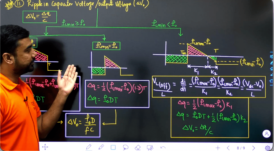
- Inductor current ripple
- Ripple output voltage
- Critical inductance
- Critical capacitance
- Diode and switch currents (average and RMS values)
Then a student can study advanced concepts like discontinuous conduction mode (DCM), multiphase converters, and non-idealities like diode voltage drop and inductor resistance with their effects on the operation of the converters. This ends the portion for GATE.
Note that no need to memorize all the formulae for this module. They can be verified easily and quickly from the basics, unlike rectifiers. With time and sufficient practice, some things get registered in the mind easily.
If you want to feel this chapter then study Power Electronics by Sohail sir. He has explained all the concepts in a very lucid manner.
For ESE, additional topics to be covered are the various control schemes, classification of converters on the basis of quadrants, operation in the various quadrants, exact analysis of type A chopper for RLE load, and C’uk converter.
(Power Electronics for GATE)
 |
 |
COMMUTATION CIRCUIT (Power Electronics for GATE)
There has been a small change in this part of the GATE 2021 syllabus. Earlier, all the types of commutation in choppers were there. Now, it is restricted to voltage and current commutated choppers only. However, for ESE, all the types need to be covered.
You can follow references 2 and 3 for this module. Before starting this part, revise the diode LC circuit from the rectifier module as it is highly used in commutation circuits. There is no generalized guideline for which parameters to be found for this module. It depends on the type of Commutation. The focus should be not on blind memorization but on how to derive the waveforms of the voltages and currents in various devices.
DC-AC CONVERTER (Power Electronics for GATE)
For this portion, you need to refer to all the references 1, 2, and 3.
First, we classify inverters as voltage source inverters (VSI) and current source inverters (CSI) and the types of power electronic switches used in each of these.
Then we study 1 phase half bridge and full bridge inverters in detail. The areas to be covered are:
- Fourier analysis of output voltage and calculation of distortion factor and total harmonic distortion THD. We also calculate the average and RMS values for the overall waveforms as well as individual harmonics.
- Behavior under various loads – R, L, RL, RC, and RLC and type of commutation for each load. Calculation of currents through the switches for each load and calculation of active and reactive power.
The next portion is pulse width modulation (PWM). First, we cover single PWM, multiple PWM, and unequal PWM with Fourier analysis of output voltage in each case. Focus has to be given to half-wave and quarter-wave symmetry and selective harmonic elimination. Then under sinusoidal pulse width modulation (SPWM), we cover the unipolar and bipolar cases. The topics to be covered are amplitude modulation index (ma), frequency modulation index (mf), expressions for fundamental output voltage, and dominant harmonics present.
(Power Electronics for GATE)
Then we deal with 3-phase VSI. Here we deal with the waveforms of various phase, line, and pole voltages for both 120° and 180° conduction modes and their Fourier analysis in a similar way as mentioned for single phase. Also, we study the firing sequence of switches for both 120° and 180° modes. The focus should be on waveforms of voltages and currents through the switches.
The final topic in this module is the current source inverter. Here both 1 and 3-phase CSI need to be covered for R, C, and RC loads. Here Fourier analysis of output voltage and current is to be done with calculation of distortion factor and THD. Various design considerations come into the picture for CSI which have to be covered too. Also, an auto sequential commutated inverter (ACSI) is to be covered.
This ends the syllabus for GATE. Further modules are only in the ESE syllabus.
AC VOLTAGE CONTROLLER (Power Electronics for GATE)
This portion is only in ESE. References 1 and 2 can be followed here. The topics to be covered are 1 and 3-phase AC voltage controllers, various methods of voltage control, equations for output voltage, the effect of source and load inductances, and the use of AC voltage controllers in tap changing of transformers.
Cycloconverters
This topic is only in the ESE syllabus. The principle of operation of cyclo converter and the implementation of various 1 and 3-phase cyclo converters with output voltage equations are to be covered. Step-up as well as step-down cycloconverters have to be covered and it is important to remember the no of thyristors required to implement each topology. This topic can be covered in references 1 and 2.
DC and AC Drives
This portion is only in the ESE syllabus. Reference book nos 3 and 6 are to be followed here. Before starting this portion, electrical machines are to be covered and revised thoroughly. This module deals with the speed control of DC motor, induction motor, and synchronous motor using power electronic converters. This much is enough for ESE.
Resonant Converters
This topic is only in the ESE syllabus. This should be covered in reference 1. The focus should be on drawing waveforms for this part. Zero voltage switching (ZVS) and zero current switching (ZCS) have to be covered here. In ZCS, both L and M types are to be covered. Comparison has to be made between ZVS and ZCS and also between resonant converters and SPWM.
High-Frequency Inductors and Transformers
This portion should be studied from reference 4. Only basic knowledge is enough in this portion.
Power Supplies
This portion is only in ESE. The topics of power supplies like SMPS, UPS, Flyback converter, Push-pull converter, etc have to be covered here in moderate detail. References 1 and 2 can be followed here.
Conclusion
The most important aspect of this subject is revision, practice, and test series. Continuous revision is a must to grasp the concepts in detail. However, if you don’t want to mess with this much content from different books, you can enroll in the Power Electronics 3.0 Course by Sohail Sir.
Some of the reviews of the Neospark Course are below:
 |
 |
 |
 |
 |
 |

Best of luck with your preparation and may out come out with flying colors.
You can reply to any query below.